Description
Wet Sludge De-liquefying
Technology
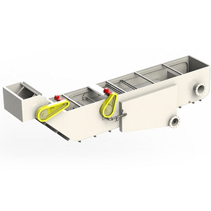
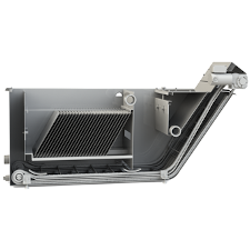
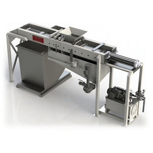
Henry Sludge Briquetter unit is designed to receive wet grinding sludge or similar compressible material for de-liquefying. After wet sludge is introduced into the inlet chute, fluid is removed from the material by means of two hydraulically operated rams. As one of the rams compresses the sludge, the fluid flows through the wedge wire screen into a catchment tray mounted below for pumping to process waste or returning to the filtration system.
Process
Wet sludge is introduced into the inlet chute from a feed conveyor or filter discharge. The Briquetter automatically senses the presence of sludge and begins a cycle. The compression ram advances pushing the wet sludge into the compression chamber. The ram retracts to allow more sludge to be added to the compression chamber. Initially, the ram compresses the sludge at a low pressure allowing the free fluid to drain out of the sludge through the wedge wire screen. As the time cycle continues, the compression pressure increases, improving the de-liquefying process. After the compression cycle is over, the plugging ram retracts opening the compression chamber, and the compression ram advances discharging the compressed brick of sludge.
Briquetter
Operation
- The Sludge Briquetter operates automatically, either when a detector senses a full load of sludge in the inlet chute, or when the manual index starts a cycle.
- Prior to completion of the compression cycle, the compression ram retracts and accepts more sludge, thus increasing capacity. Pressure on the sludge is applied at an increasing rate to maximize the deliquefying process.
- During the compression cycle, the fluid in the sludge is recovered to the tray under the unit. Recovered fluid can be drained, pumped back to the filter system, or process waste.
- After the compression cycle is complete, the plugging ram retracts, allowing the compression ram to extend, and the de-liquefied swarf to be ejected for recycling or disposal.
- Once the compressed swarf is ejected both cylinders return to the home position for the start of another cycle.
System Benefits
- Automatic operation
- Minimum floor space required
- Recovers valuable oil or coolant
- Produces dry sludge for over-the-road transportation, recycling, and recovery/disposal
- Replaceable stainless steel de-liquefying screen panel
- Compact design allows installation under filter discharge ramp
- Return on investment can be less than 1 year, due to savings from salvaged fluid or disposal costs of swarf.